News information
Category:Industry Information Date:2023-07-07 View:342
Create 360° Bird's-Eye-View Image Around a Vehicle
This example shows how to create a 360° bird's-eye-view image around a vehicle for use in a surround view monitoring system. It then shows how to generate code for the same bird's-eye-view image creation algorithm and verify the results.
Overview
Surround view monitoring is an important safety feature provided by advanced driver-assistance systems (ADAS). These monitoring systems reduce blind spots and help drivers understand the relative position of their vehicle with respect to the surroundings, making tight parking maneuvers easier and safer. A typical surround view monitoring system consists of four fisheye cameras, with a 180° field of view, mounted on the four sides of the vehicle. A display in the vehicle shows the driver the front, left, right, rear, and bird's-eye view of the vehicle. While the four views from the four cameras are trivial to display, creating a bird's-eye view of the vehicle surroundings requires intrinsic and extrinsic camera calibration and image stitching to combine the multiple camera views.
In this example, you first calibrate the multi-camera system to estimate the camera parameters. You then use the calibrated cameras to create a bird's-eye-view image of the surroundings by stitching together images from multiple cameras.
Calibrate the Multi-Camera System
First, calibrate the multi-camera system by estimating the camera intrinsic and extrinsic parameters by constructing a monoCamera object for each camera in the multi-camera system. For illustration purposes, this example uses images taken from eight directions by a single camera with a 78˚ field of view, covering 360˚ around the vehicle. The setup mimics a multi-camera system mounted on the roof of a vehicle.
Estimate Monocular Camera Intrinsics
Camera calibration is an essential step in the process of generating a bird's-eye view. It estimates the camera intrinsic parameters, which are required for estimating camera extrinsics, removing distortion in images, measuring real-world distances, and finally generating the bird's-eye-view image.
In this example, the camera was calibrated using a checkerboard calibration pattern in the Using the Single Camera Calibrator App and the camera parameters were exported to cameraParams.mat. Load these estimated camera intrinsic parameters.
ld = load("cameraParams.mat");
Since this example mimics eight cameras, copy the loaded intrinsics eight times. If you are using eight different cameras, calibrate each camera separately and store their intrinsic parameters in a cell array named intrinsics.
numCameras = 8;
intrinsics = cell(numCameras, 1);
intrinsics(:) = {ld.cameraParams.Intrinsics};
Estimate Monocular Camera Extrinsics
In this step, you estimate the extrinsics of each camera to define its position in the vehicle coordinate system. Estimating the extrinsics involves capturing the calibration pattern from the eight cameras in a specific orientation with respect to the road and the vehicle. In this example, you use the horizontal orientation of the calibration pattern. For details on the camera extrinsics estimation process and pattern orientation, see Calibrate a Monocular Camera.
Place the calibration pattern in the horizontal orientation parallel to the ground, and at an appropriate height such that all the corner points of the pattern are visible. Measure the height after placing the calibration pattern and the size of a square in the checkerboard. In this example, the pattern was placed horizontally at a height of 62.5 cm to make the pattern visible to the camera. The size of a square in the checkerboard pattern was measured to be 29 mm.
% Measurements in meters
patternOriginHeight = 0.625;
squareSize = 29e-3;
The following figure illustrates the proper orientation of the calibration pattern for cameras along the four principal directions, with respect to the vehicle axes. However, for generating the bird's-eye view, this example uses four additional cameras oriented along directions that are different from the principal directions. To estimate extrinsics for those cameras, choose and assign the preferred orientation among the four principal directions. For example, if you are capturing from a front-facing camera, align the X- and Y- axes of the pattern as shown in the following figure.
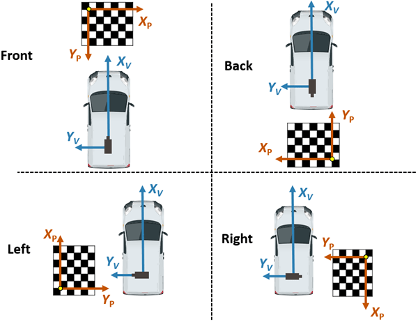
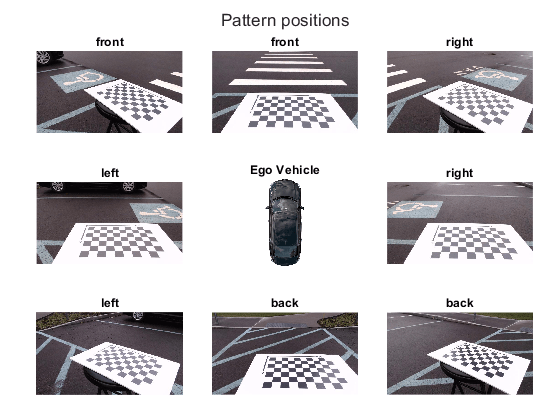
The variable patternPositions stores the preferred orientation choices for all the eight cameras. These choices define the relative orientation between the pattern axes and the vehicle axes for estimateMonoCameraParameters function. Display the images arranged by their camera positions relative to the vehicle.
patternPositions = ["front", "left" , "left" , "back" ,...
"back" , "right", "right", "front"];
extrinsicsCalibrationImages = cell(1, numCameras);
for i = 1:numCameras
filename = "extrinsicsCalibrationImages/extrinsicsCalibrationImage" + string(i) + ".jpg";
extrinsicsCalibrationImages{i} = imread(filename);
end
helperVisualizeScene(extrinsicsCalibrationImages, patternPositions)
To estimate the extrinsic parameters of one monocular camera, follow these steps:
In this example, the setup uses a single camera that was rotated manually around a camera stand. Although the camera's focal center had moved during this motion, for simplicity, this example assumes that the sensor remained at the same location (at origin). However, distances between cameras on a real vehicle can be measured and entered in the sensor location property of monoCamera.
monoCams = cell(1, numCameras);
for i = 1:numCameras
% Undistort the image.
undistortedImage = undistortImage(extrinsicsCalibrationImages{i}, intrinsics{i});
% Detect checkerboard points.
[imagePoints, boardSize] = detectCheckerboardPoints(undistortedImage,...
"PartialDetections", false);
% Generate world points of the checkerboard.
worldPoints = generateCheckerboardPoints(boardSize, squareSize);
% Estimate extrinsic parameters of the monocular camera.
[pitch, yaw, roll, height] = estimateMonoCameraParameters(intrinsics{i}, ...
imagePoints, worldPoints, patternOriginHeight,...
"PatternPosition", patternPositions(i));
% Create a monoCamera object, assuming the camera is at origin.
monoCams{i} = monoCamera(intrinsics{i}, height, ...
"Pitch", pitch, ...
"Yaw" , yaw, ...
"Roll" , roll, ...
"SensorLocation", [0, 0]);
end
Create 360° Bird's-Eye-View Image
Use the monoCamera objects configured using the estimated camera parameters to generate individual bird's-eye-view images from the eight cameras. Stitch them to create the 360° bird's-eye-view image.
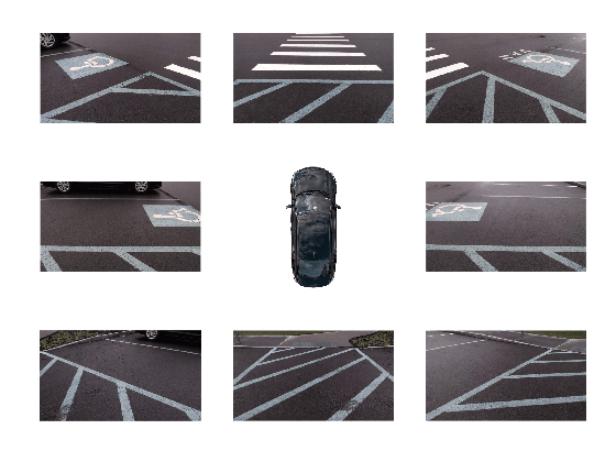
Capture the scene from the cameras and load the images in the MATLAB workspace.
sceneImages = cell(1, numCameras);
for i = 1:numCameras
filename = "sceneImages/sceneImage" + string(i) + ".jpg";
sceneImages{i} = imread(filename);
end
helperVisualizeScene(sceneImages)
Transform Images to Bird's-Eye View
Specify the rectangular area around the vehicle that you want to transform into a bird's-eye view and the output image size. In this example, the farthest objects in captured images are about 4.5 m away.
Create a square output view that covers 4.5 m radius around the vehicle.
distFromVehicle = 4.5; % in meters
outView = [-distFromVehicle, distFromVehicle, ... % [xmin, xmax,
-distFromVehicle, distFromVehicle]; % ymin, ymax]
outImageSize = [640, NaN];
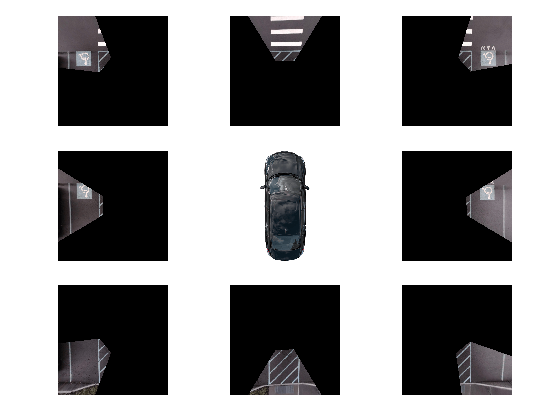
To create the bird's-eye-view image from each monoCamera object, follow these steps.
bevImgs = cell(1, numCameras);
birdsEye = cell(1, numCameras);
for i = 1:numCameras
undistortedImage = undistortImage(sceneImages{i}, monoCams{i}.Intrinsics);
birdsEye{i} = birdsEyeView(monoCams{i}, outView, outImageSize);
bevImgs{i} = transformImage(birdsEye{i}, undistortedImage);
end
helperVisualizeScene(bevImgs)
Test the accuracy of the extrinsics estimation process by using the helperBlendImages function which blends the eight bird's-eye-view images. Then display the image.
tiled360DegreesBirdsEyeView = zeros(640, 640, 3);
for i = 1:numCameras
tiled360DegreesBirdsEyeView = helperBlendImages(tiled360DegreesBirdsEyeView, bevImgs{i});
end
figure
imshow(tiled360DegreesBirdsEyeView)
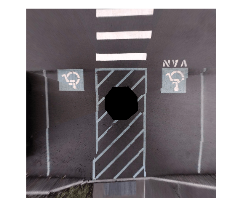
For this example, the initial results from the extrinsics estimation process contain some misalignments. However, those can be attributed to the wrong assumption that the camera was located at the origin of the vehicle coordinate system. Correcting the misalignment requires image registration.
Register and Stitch Bird's-Eye-View Images
First, match the features. Compare and visualize the results of using matchFeatures with matchFeaturesInRadius, which enables you to restrict the search boundary using geometric constraints. Constrained feature matching can improve results when patterns are repetitive, such as on roads, where pavement markings and road signs are standard. In factory settings, you can design a more elaborate configuration of the calibration patterns and textured background that further improves the calibration and registration process. The Feature Based Panoramic Image Stitching example explains in detail how to register multiple images and stitch them to create a panorama. The results show that constrained feature matching using matchFeaturesInRadius matches only the corresponding feature pairs in the two images and discards any features corresponding to unrelated repetitive patterns.
% The last two images of the scene best demonstrate the advantage of
% constrained feature matching as they have many repetitive pavement
% markings.
I = bevImgs{7};
J = bevImgs{8};
% Extract features from the two images.
grayImage = rgb2gray(I);
pointsPrev = detectKAZEFeatures(grayImage);
[featuresPrev, pointsPrev] = extractFeatures(grayImage, pointsPrev);
grayImage = rgb2gray(J);
points = detectKAZEFeatures(grayImage);
[features, points] = extractFeatures(grayImage, points);
% Match features using the two methods.
indexPairs1 = matchFeaturesInRadius(featuresPrev, features, points.Location, ...
pointsPrev.Location, 15, ...
"MatchThreshold", 10, "MaxRatio", 0.6);
indexPairs2 = matchFeatures(featuresPrev, features, "MatchThreshold", 10, ...
"MaxRatio", 0.6);
% Visualize the matched features.
tiledlayout(1,2)
nexttile
showMatchedFeatures(I, J, pointsPrev(indexPairs1(:,1)), points(indexPairs1(:,2)))
title(sprintf('%d pairs matched\n with spatial constraints', size(indexPairs1, 1)))
nexttile
showMatchedFeatures(I, J, pointsPrev(indexPairs2(:,1)), points(indexPairs2(:,2)))
title(sprintf('%d pairs matched\n without spatial constraints', size(indexPairs2,1)))
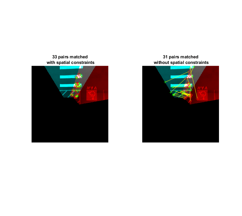
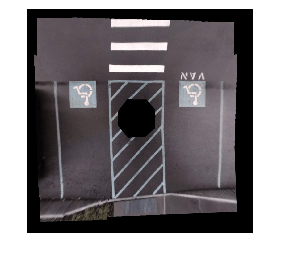
The functions helperRegisterImages and helperStitchImages have been written based on the Feature Based Panoramic Image Stitching example using matchFeaturesInRadius. Note that traditional panoramic stitching is not enough for this application as each image is registered with respect to the previous image alone. Consequently, the last image might not align accurately with the first image, resulting in a poorly aligned 360° surround view image.
This drawback in the registration process can be overcome by registering the images in batches:
Note the use of larger matching radius for stitching images in step 3 compared to steps 1 and 2. This is because of the change in the relative positions of the images during the first two registration steps.
% Cell array holding two sets of transformations for left and right sides
finalTforms = cell(1,2);
% Combine the first four images to get the stitched leftSideview and the
% spatial reference object Rleft.
radius = 15;
leftImgs = bevImgs(1:4);
finalTforms{1} = helperRegisterImages(leftImgs, radius);
[leftSideView, Rleft] = helperStitchImages(leftImgs, finalTforms{1});
% Combine the last four images to get the stitched rightSideView.
rightImgs = bevImgs(5:8);
finalTforms{2} = helperRegisterImages(rightImgs, radius);
rightSideView = helperStitchImages(rightImgs, finalTforms{2});
% Combine the two side views to get the 360° bird's-eye-view in
% surroundView and the spatial reference object Rsurround
radius = 50;
imgs = {leftSideView, rightSideView};
tforms = helperRegisterImages(imgs, radius);
[surroundView, Rsurround] = helperStitchImages(imgs, tforms);
figure
imshow(surroundView)
Measure Distances in the 360° Bird's-Eye-View
One advantage in using bird's-e
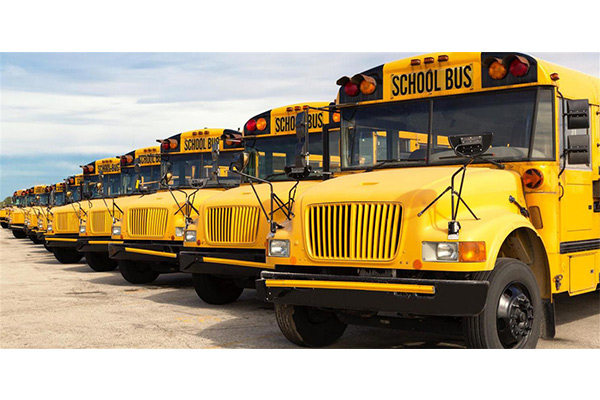
School buses are the safest way to get children to and from school, School bus CCTV equipment Basic surveillance camera systems for buses usually come with 8 or fewer cameras, a mobile digital video recorder (DVR), GPS (or routing software), and recording software (with time stamps and detailed bus signals) for reviewing.
Video cameras are becoming a necessity in society today. Video surveillance can reduce diverse safety risks on as well as off the bus. The American School Bus Council has reported that each year school buses are transporting more than 25 million children from and to school.
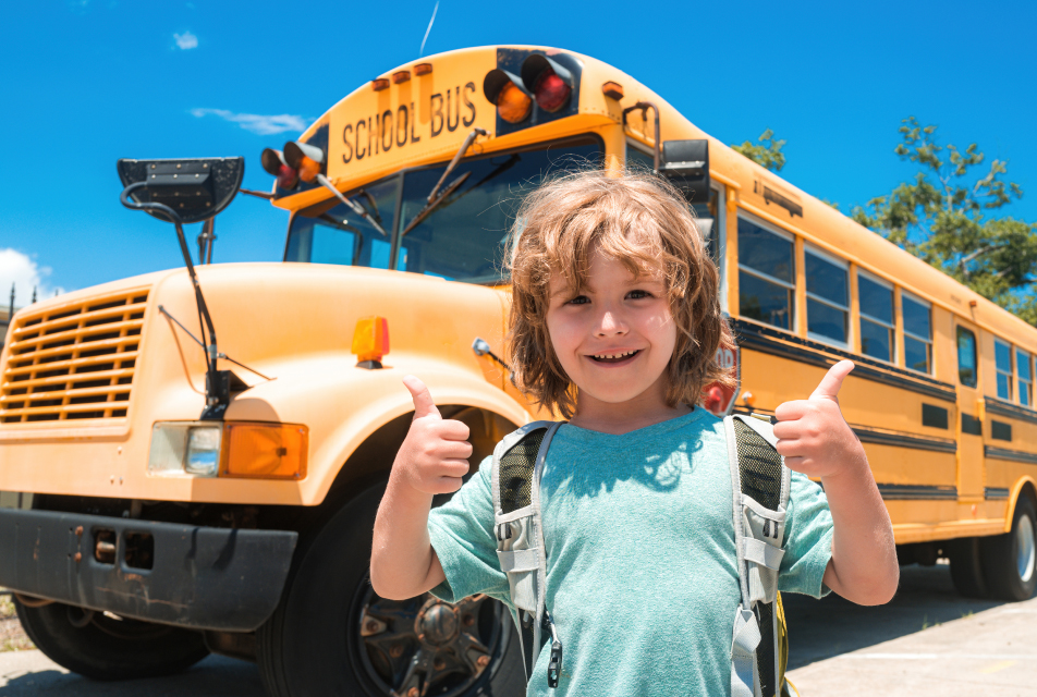
School Bus Transportation has been more and more important in whole world , with the increasing accident happened and many problems coming , which need to solved, for example, on the behavior of the students on the buses, fixing of the bus stops by the schools, handling of complaints from the parents (in some cases these go directly to the principal), reservation of seats or fixed seats on the transport, eating and drinking aboard the buses, compulsory use only those buses on which students have been allotted a seat (and not any school bus), how/where the buses are supposed to pick/drop the students, how buses must be marked, etc.
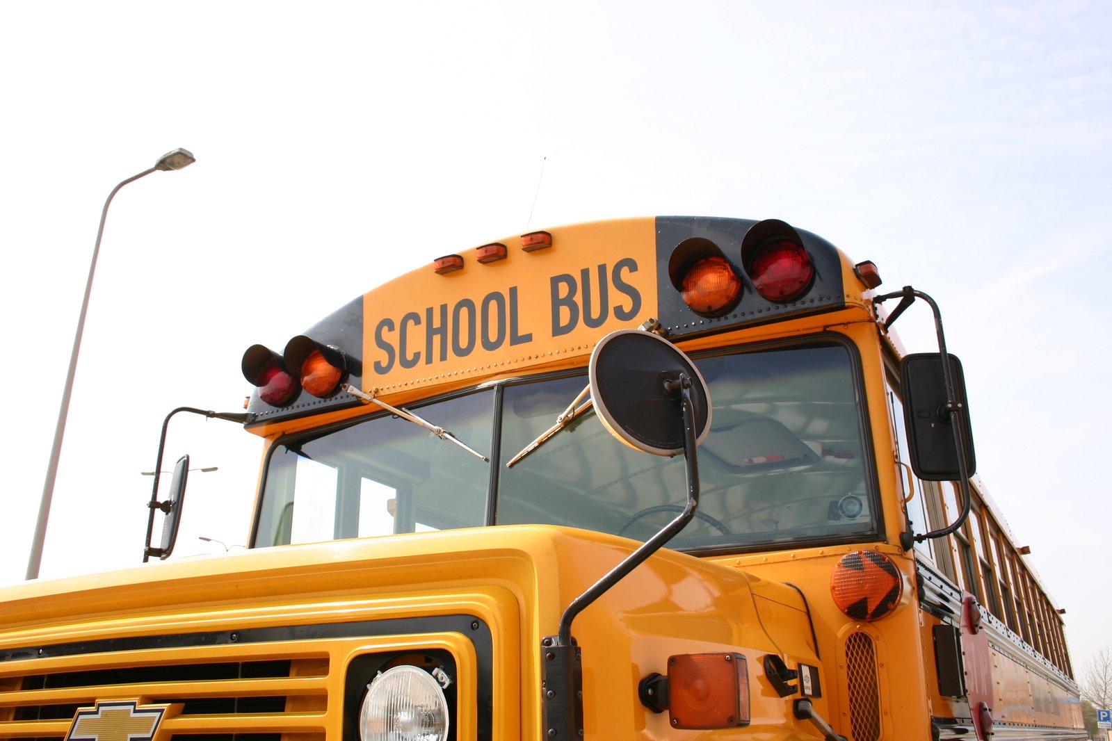
School bus camera systems are a valuable tool for school administrators looking for a proactive approach to student and staff safety. These systems monitor student and driver behavior and help maintain order while providing peace of mind for parents and administrators. When installed correctly, school bus cameras should provide clear views of critical areas in the interior and exterior of the bus. These include views of the exits, the driver, passengers, the road ahead, and the stop arm. A proper system can also provide real-time response through live stream viewing and an emergency alert button for the driver to alert school personnel when an incident occurs.